Tuesday, 31 October 2017

Behind the scenes Part 4: Giant fullerene formation through thermal treatment of fullerene soot

This is the final blog post in the series on the paper we recently published on the formation of giant fullerenes (see pt1, pt2 and pt3). In these posts I have been going behind the scenes looking at the techniques and results in context and in less technical language. In this post, I will talk about what holds the fullerenes to the soot during the heating and also look at how large we could make these giant fullerenes.

Link to all of the blog posts on the paper
Part 1 - Energetically fullerenes are unstable and want to coalescence
Part 2 - Weighing fullerenes as they grow
Part 3 - Viewing fullerenes coalescing

Part 4 - Simulating how large we can grow giant fullerenes (this page)

How do the small cages stick to the soot at high temperatures?


Oxygen is the short answer. The long answer involves another complex looking instrument called an x-ray photoelectron spectrometer, or XPS for short.

Credit: nottingham
Briefly this instrument uses x-rays to excite electrons from the very centre of the atom into the vacuum. The speed of these electrons is then measured to allow the strength of the binding between the core electron and the nuclei to be determined. The reason this instrument is so useful is that small changes in the binding energy of the electrons in the very centre of the atom (core electrons) tells you what is bonded to that atom. Here is a link to a video explaining the instrument in more detail if you are interested.

Oxygen is known to stick to fullerenes easily and to react with fullerenes and irreversibly become integrated into fullerenes when heated. This is why fullerene soot has a shelf life. The mass spectrum below left revealed peaks indicating one two or three oxygen becoming integrated into the fullerenes The XPS spectrum of the carbon in the soot (shown right) shows the integrated oxygen the single bonded form and form crosslinks C-O-C while the carbonyl oxygen cannot C=O.


The C-O-C peak indicates oxygen is acting as a bridging species between the fullerenes and the carbon and also between fullerene cages. Oxygen has previously been shown to anchor fullerenes to nanocones. This would allow the fullerenes to be held to the surface and allow them to coalescence. 

We also explored the coalescence of fullerenes bridged by oxygen using a molecular dynamic forcefield that allowed bonds to break and form called ReaxFF.

Similar dynamics can be seen between the all carbon fullerenes coalescing and the oxy-fullerenes. The coalescence is known to be enhanced with oxygen. This could be due to the anchoring effect which makes it more likely they will coalesce or due to relieving the strain at the neck between the fullerenes as they coalescence.


How big can we make them?


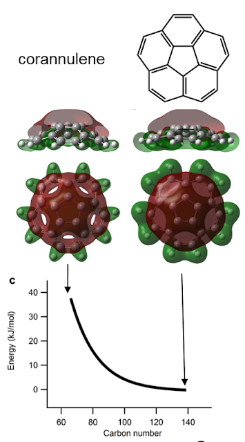
The question of what maximum sized cage can be made is wrapped up with the question of what drives the coalescence. It is known that the top and bottom surface of graphite is not reactive and only when you add in a pentagon and strain the structure does it become reactive. This has also been shown with simulations of fullerenes fusing. We, therefore, considered only the pentagon as being the reactive site. As the fullerenes become smaller the pentagon site becomes more strained. We simulated this by puckering a small bowl molecule that is the simplest curved subunit corannulene. This straining could be related with a certain increase in the energy and we hypothesised that the higher reactivity of the smaller cages is linearly dependent with this energy (Bell-Evans-Polanyi principle).

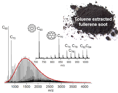
To see if this scaling is appropriate we chose a simple system the laser ablation and detection of C60 and C70 in a mass spectrometer (the toluene extract from the soot extraction process was used). We used a high laser power to produce dimers and trimers of C60 and C70. In the gas phase you can assume only two molecules are reacting at a time and this lets you write down a set of equation you can solve using the computer. Below the experimental and simulation mass spectra can be compared. 


The simulation was able to describe the formation of dimers and trimers. Differences between the experiment and the simulation include the right skew to the mass spectrum in the experiment which is due to C2 being ejected. Another difference is the higher concentration of C60 and C70 dimers indicating that C60 and C70 are indeed less reactive than the other cages. The reasonable agreement with the size of fragments that are formed suggests the coalescence at low temperatures is driven by the strain at the pentagonal carbon atoms. This would allow cages up to ~300 carbon atoms to be formed from low temperature strain driven reactions. Below is an interactive 3D model of $\text{C}_{320}$ click and drag the structure to see the structure of a similar sized giant fullerene.


So what?

The first thing these results allowed us to do is comment on fullerene formation mechanisms. The mass spectrum provides a second experimental validation of the log-normal distribution of fullerene cages found previously in the gas phase. This log-normal distribution indicates a process of size dependent growth and/or coalescence occurring. This rules out some mechanisms where the fullerenes remain in contact and exchange carbon, which is seen in droplets (Ostwald ripening). This would produce a distribution skewed towards the higher masses which is the opposite of what is observed. Also, disproportionation reactions would lead to a normal distribution of masses as shown by Curl et al. which is not seen. The log-normal distribution could be achieved through $\text{C}_2$ ingestion/ejection where the smaller fullerenes are more reactive to free $\text{C}_2$. Or by fullerenes in the gas phase fragmenting and coalescing dynamically. We are currently working on the kinetic model to include these features.

The second comment is on how you would go about making greater quantities of giant fullerenes preferably without oxygen. One option is to modify the arc synthesis of fullerenes, by providing more time and higher temperatures inside the carbon plasma you could tuned the reactor to produce larger structures.

Finally, the internal volume of these larger fullerenes are significantly larger than the magic number fullerene C$_{60}$ and C$_{70}$ and there is potential to trap inside the cages many atoms or even perhaps molecules. It is also an interesting thought to consider how much bigger these fullerenes could be produced. The paper mentioned in the first blog post of shrinking giant fullerenes imaged much larger fullerenes C$_{1000}$ which are thought to come from nanotubes in that study. This suggests further enlarging is possible.

If you got through all of those blog posts well done! Please post any comments if you have any questions about the methods used or the interpretation of the results.

Monday, 30 October 2017

Behind the scenes Part 3: Giant fullerene formation through thermal treatment of fullerene soot

This is the third blog in the series on a new paper we have written (see pt1 and pt2) going behind the scenes on the techniques used and explaining the significance of the results. In this post, I will talk about what happened when we heated the fullerene soot which we extracted the C60 and C70 from, and what happened to the fullerenes bigger than C70. To see this, we made use of an electron microscope (which I can guarantee is not a hoax - they really do work and produce some amazing images).

Link to all the blog posts on the paper
Part 1 - Energetically fullerenes are unstable and want to coalescence
Part 2 - Weighing fullerenes as they grow
Part 3 - Viewing fullerenes coalescing (this page)
Part 4 - Simulating how large we can grow giant fullerenes

Fusing fullerenes together

We prepared high-temperature reaction chambers by using a hydrogen torch to seal off one end of a hollow quartz tube.


We then added the toluene-extracted fullerene soot into the tube, which was placed in a furnace and heated at different temperatures for an hour. A vacuum pump was used to remove gas phase fullerenes to make sure we were only reacting fullerenes in the solid state.


Electron microscope

In order to look at how the molecules were transforming as we heated them, we made use of an amazing instrument called a transmission electron microscope (the Tecnai F20). It had just recently been purchased so Dr Shanghai Wei helped us with the alignment and capturing the images.


An electron microscope makes use of electrons instead of light to produce images of molecules or even single atoms. To explain their operation it is helpful to compare the electron microscope with an old CRT (cathode ray tube) monitor and an optical microscope. If you are unfamiliar with a cathode ray tube CRT here is a short video explaining them. 

You can think of an electron microscope as a combination of an old CRT monitor and an optical microscope. One reason why both the CRT and TEM have to be operated in vacuum is that the electrons would collide with gas molecules in the air and would not be able to travel more than a few millimetres. Electrons are produced quite simply by heating up a wire and charging it with a negative voltage, allowing the electrons to boil off. These electrons are then pushed into the main column by an electric field and electromagnets are used in a similar way to optical lenses in a microscope to condense and focus the light to a tiny spot in the sample. 


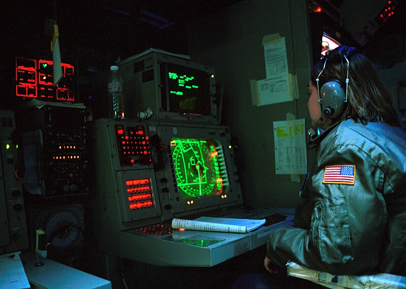
After the electrons pass through the sample they are expanded and hit a phosphor screen forming a green image. These phosphor screens might be more familiar to you from submarine movies that show green radar screens. 


It is quite magical when you open up the column valve and see this green spot form on the saucer which is inside the high vacuum chamber. As you focus the image using a knob on the left of the console, an image of the molecules comes into focus. I have added in a Youtube video so you can also experience the excitement.
https://cemas.osu.edu/fei-tecnai-f20-stem

Pictures are then taken on a camera hiding under the green screen which can be raised letting the electron beam focus onto a camera.

Making giant fullerenes

Below are the results for the heated sample. Collecting the mass spectrum for the heated soot using the mass spectrometer (which I spoke about in the last post) we found the distribution of mass peaks shifted towards higher masses. Imaging the edge of the soot using the electron microscope we could see small dark fringes which are the fullerene molecules. When you heat the sample, these small closed fringes are seen to enlarge. It is mind-blowing to think these cages are only a nanometre wide (that is 0.000000001 m, or a million times smaller than a metre). For some more help with the scale, you could line up 50,000 of these nanometre-sized cages and they would just be as thick as your hair.

We wanted to see the fullerenes as they were being heated to observe the tranformation in real time, so we increased the temperature of the wire in the electron gun, increasing the number of electrons boiling off the wire and flooding the sample with a very intense beam of electrons. This increased the temperature of the sample and allowed us to view the sample changing. You can see after 11 minutes of irradiation a smaller fullerene attached to a larger fullerene (indicated by the arrow) and then fused with it over the next nine minutes.


Here is one of the earlier videos I took of the computer screen as the sample was irradiated.


The observation of small fullerenes coalescing into larger fullerenes had never been observed before so it was very exciting to see this as it happened. The next blog post will involve some computer simulations to see how large, theoretically, these cages can become and also consider what we might do with them. 

Tuesday, 24 October 2017

Behind the scenes Part 2: Giant fullerene formation through thermal treatment of fullerene soot

This is the second installment of a blog series going behind the scenes on the recent paper "Giant fullerene formation through thermal treatment of fullerene soot". Last time I talked about the motivation for doing experiments on fullerenes. The idea that larger fullerenes are more stable than small fullerenes such as C60 or C70. This week I want to show you the distribution of fullerenes in the solid state.

Link to all the blog posts on the paper

Weighing fullerenes

The first thing to do was to see if we could observe the higher fullerenes in fullerene soot otherwise we would not know what was happening to them. I got in contact with Dr Angus Grey from the Biomedical imaging centre at the University of Auckland. He had recently acquired a mass spectrometer for the biomedical imaging research unit to analyse proteins in biological samples such as brain slices. The mass spectrometer instrument the UltrafleXtreme is one of the highest resolution mass spectrometers in the world over a large mass range (the large mass range is needed to look at proteins or in our case fullerenes). Below is a short video showing the basic idea of using a laser to produce charged molecules (ions) which can be pushed with an electric field into the chamber. The heavier ions will be accelerated to a lower speed than the lighter ones so the lighter molecules will reach the detector before the heavier ions where they are detected (by the electrons they emit when they hit the detector). This timed flight is a very accurate method to determine the mass of heavy ions.


The instrument is fairly impressive taking up a room in the basement.  

Below is a picture of the inside of the device. The large tube is where the molecules are accelerated into and then reflected back to the detector to increase the distance they travel. 
Credit
The schematic below shows the path of the charged molecules inside of the instrument. In the case of analysing fullerene molecules, the laser excites the fullerene cages and ejects an electron from the molecule this gives the fullerenes a positive charge which allows them to be manipulated inside the instrument using electric fields.

Credit: Bruker
The mass spectrum which you measure on the computer looks like a collection of spikes they indicate the mass divided by the charge (m/z) of a molecule or collection of molecules with the same mass and charge (in our case the main ions from fullerenes have a single charge +1 so the spikes corresponds to the molecular mass of the fragments). The molecular mass of carbon is 12 g/mol so the spike/peak at 720 m/z is for C60 and the spike/peak at 840 m/z is C70. The higher fullerenes Cn>70 are much lower in concentration than C60 and C70 and are really hard to see so we added an inset showing the spectrum from 1000-5000 m/z multiplied by 150 in the figure below.

You can see a range of spikes between 1000-3000 m/z. They are separated by 24 m/z which corresponds to two carbon atoms. Fullerenes only lose or gain carbon in pairs due to the C2 dimers being very stable. So this comb of spikes separated by C2 indicates the comb are fullerenes. The laser is not continuously on by emits a short pulse of light and the power of that pulse can be reduced. We found we needed quite a high laser power to have enough energy in the laser pulse to see this comb of higher fullerenes. We think this is because there is quite a bit of C60 and C70 which absorbs most of the laser light. Unfortunately, the high laser power meant the C60 and C70 broke apart you can see this in the figure above if you look to the left of C60 and C70. C58 and C56, as well as C68 and C66 spikes, are seen indicating C60 and C70 are fragmenting and losing carbon. We also saw evidence for small fragments being formed. If you look at the figure below where we stacked mass spectra from lowest laser power (bottom) to highest laser power (top) see small fragments can be seen between 0-300 m/z being formed as you increase the laser power.
This is not what we want as this indicates the distribution is being changed from reactions happening after the laser has excited the molecules in the sample. Our focused changed to working out a way of reducing the amount of C60 and C70 in the fullerene soot to try and more easily observe the higher fullerenes. Due to C60 and C70's high symmetry, they are more easily dissolved in solvents like toluene while the higher fullerenes are quite insoluble. So we used a piece of glassware called a Soxhlet extractor to extract the C60 and C70 using the solvent toluene.

Some proper chemistry

Soxhlet extraction involves a really neat piece of glassware. You put your sample into a porous vial and place it into the middle section. The solvent, in our case toluene, is then added to a round bottom flask and heated up. The hot toluene vapour travels up a tube around the side of the middle section into a condenser which has cold water flowing around the outside of it. This cools down the toluene and forms liquid droplets which then drop onto the vial in the middle section. The fullerenes C60 and C70 dissolve into the toluene and give a nice pink colour. Once the middle section fills up and reaches the top of the siphon tube all of the toluene in the middle section siphons out, back into the round bottom flask. The neat thing is that each time the middle section fills with toluene it has fresh toluene without fullerenes present as the toluene vapor formed cannot hold any fullerenes due to the much higher vaporisation temperature of fullerenes. This improves the efficiency of the extraction. This extraction and siphoning repeats every 5-10 minutes and we left this running for 48 hours so this processes must have repeated over 250 times.
https://commons.wikimedia.org/wiki/File:Soxhlet_mechanism.gif 
By the end you can see the liquid in the round bottom flask has a nice pink colour full of C60 and C70. While the middle section is a clear liquid meaning all of the soluble C60 and C70 has been pulled out of the soot.


The distribution of higher fullerenes

We then analysed the soot again with the mass spectrometer (figure below) and you can see a much lower amounts of C60 and C70. This meant we could use much lower laser powers which gave no small fragments and no noticeable fragmentation. Below is a figure of what we found. A nice comb of spikes corresponding to fullerenes from C60 to C200.
The concentration of the higher fullerenes follows a function called a log-normal distribution (shown in red above) this indicates coalescence processes are involved in the formation mechanism. This log-normal size distribution is commonly associated with coalescence reactions where the smaller structure more easily coalescence due to weighing less or being more reactive.
Credit: link
In the next blog post, I will show what impact heating the fullerene soot with the C60 and C70 extracted has on the mass distribution of higher fullerenes.